PETAMENTOR — How to: Part 1 (Platform)
Build the base board for the first PETAMENTOR prototype. Recommended size: ≈ 500 × 150 × 16 mm.
Table of Contents
Overview & Why size matters
The base for building PETAMENTOR is a wooden shelf board about 500 × 150 × 16 mm. Using a noticeably smaller board is not recommended: each component needs space without compromise — from the entry of the cut PET strip, through the hot-end/nozzle, to the winder. A larger, rigid base lets you fine-tune the strip’s path and helps reduce resistance during melting and winding.
Materials
- Shelf board (MDF or particle board), about 500 × 150 × 16 mm
- Optional edge band / trim tape
- 4× cylindrical furniture legs (with screws/washers supplied)
Tools
- Measuring tape, square, pencil/marker
- Saw (hand saw or circular saw), sanding/deburring block
- Drill/screwdriver; wood drill bits for pilot holes
- Knife for trimming edge band
- Vacuum/brush and a clean cloth
Safety & preparation
Work safely: clamp the board before cutting, wear eye protection and a dust mask, and keep hands clear of the blade. Pre-drill pilot holes to avoid splitting.
Step-by-step guide
-
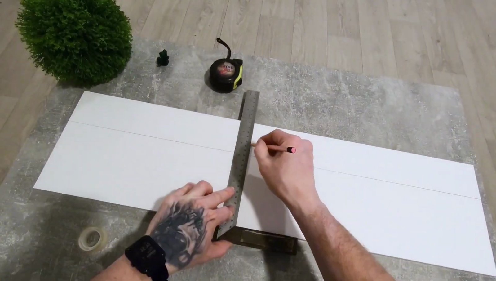
Measure & mark the board to the target size. Use a square so the cut stays true.
Accurate layout at the start saves time later. -
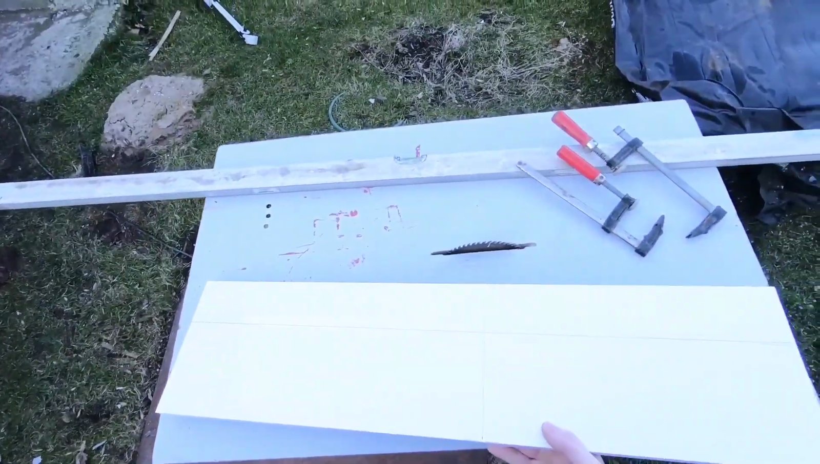
Cut to length. Support the board well, then deburr the fresh edge.

-
(Optional) Apply edge band/trim. Press firmly and trim overhangs for a clean, chip-resistant edge.

-
Plan the leg positions. Place four legs near the corners with a small inset from each edge for stability and screw clearance
(a practical starting point is about 20–30 mm; adjust to your leg hardware).

-
Pre-drill pilot holes according to your screw size. This prevents splitting and keeps screws straight.

-
Mount the legs and tighten the screws. Use washers if needed.

-
Final check. Flip the platform upright, confirm it sits flat, and re-tighten if necessary. The base is ready for the next PETAMENTOR modules.

Tips
- Do not reduce the base size significantly — you’ll need room to tune the PET strip path from bottle entry to nozzle to winder.
- Keep the top surface smooth; it doubles as a layout reference for straight geometry.
- Rubber feet on the legs help reduce vibrations during winding.
- Consider marking a light mounting grid (e.g., 20 mm spacing) on the underside for repeatable placements.
Video & timeline
Approximate chapters: 00:00 Title · 00:25 Measure & mark · 00:50 Cut · 02:05 Indoors prep · 03:25 Edge band · 05:05 Parts layout · 05:35 First leg · 06:50 Pre-drill · 07:40 Mount legs · 08:10 Finished platform.