PETAMENTOR — How to: Part 2 (Puller & Winder basics)
Assemble the puller module (rollers & drive) and upgrade the winder with a flanged shaft hub to stop spool slip.
Table of Contents
Overview
The puller provides controlled traction on the PET strip using two rollers. Correct alignment and gentle pressure are key to avoid deformation while maintaining grip. Additionally, the winder benefits from a simple upgrade — a flanged shaft hub — installed between the motor shaft and the spool hub to eliminate slipping under load.

Materials
- Puller rollers (pair) with shaft and bearings
- Mounting brackets and fasteners
- Drive motor with pulley (or direct drive)
- Guide(s) for strip entry/exit
- Flanged shaft hub (for winder anti-slip, see upgrade below)
Tools
- Hex keys, screwdriver
- Drill for pilot holes if needed
- Square/ruler for alignment
Safety
Keep fingers away from the drill bit :-); Verify all rotating parts are secured before testing.
Step‑by‑step — Puller
-
Solder about a 40cm of wire to a 12V 7RPM DC motor.

Soldering the wires. -
Assemble the brackets on a DC motor.

-
Center the puller and make marks to drill the holes for screws.

-
Install the motor (and pulley if used); align with the roller axis.
-
Adjust roller pressure (pinch) — firm grip without deforming the strip.

-
Thread the PET strip through the rollers; hand-rotate to verify smooth feed.

-
First powered run: check traction and correct any wandering.

-
Fine alignment: keep the path straight to the winder.

-
Steady pull: verify constant speed under light load.

-
Final check: tighten hardware and confirm no rubbing or vibration.

Upgrade — Flanged shaft hub (Winder)
Purpose: Couples the spool directly to the motor shaft to eliminate slippage under load.
Where it goes: Install between the motor shaft and the spool hub on the winder.
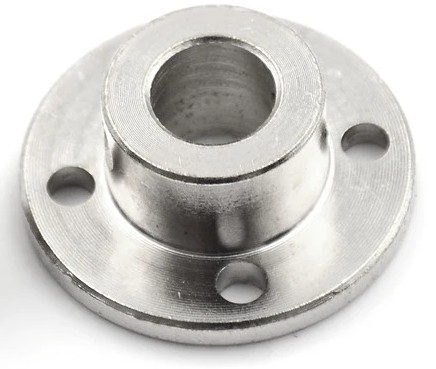
Quick procedure
- Seat the flanged hub on the spool hub (holes aligned) and secure per your hardware.
- Slide the assembly onto the clean motor shaft and lock the hub to the shaft.
- Spin by hand to check run‑out; re‑seat if needed. Re‑check after first warm run.
Video & timeline
Approximate chapters: overview · assembly · motor · threading · first run · alignment · steady run · upgrade (flanged hub).